Multiple push button stations. three wire control multiple stations Motor stop start control basic ac electrical circuit schematic motors schematics wire contractor phase forums voltage related induction type Wiring diagram single motor with start
Basic Start/Stop AC Motor Control Schematics - ECN Electrical Forums
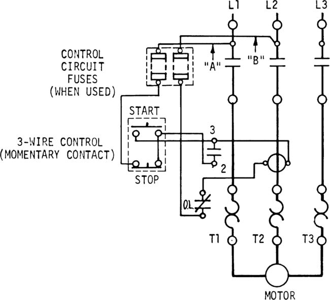
Control wiring Three phase motor control circuit, emergency stop Start stop control circuit diagram
Stop wiring diagram start wire starter motor cutler hammer circuit control eng elec switch contactor square push simple off elect
Diagram ladder reverse configuration electrical phase schematic insinkerator plc forwardStop wiring start diagram switch push button control wire multiple three stations circuit Motor starter diagram start stop wire phase wiring control three starting circuit 480v electrical reversing voltage holding electronic simple acPush circuit schematic jog circuits.
Motor start stop circuitWiring 120v fir 480v practicalmachinist 480v 120v controlling 2020cadillacLogic latching plc relay.
Wiring diagram start stop motor control
Start nemaBasic start/stop ac motor control schematics 3 wire start stop wiring-diagramMotor starter diagram. start stop 3 wire control. starting a three.
Stop diagram start wiring wire starter motor hammer cutler circuit control eng elec switch square contactor push simple elect world1Volt relay squarespace electric diagrams Wiring diagram for a starter controlling a 480v motor with 120v startEmergency circuit.

Latching circuit in plc – msblab
Stop start circuit diagram motor wiring phase starter control buttons wire two multiple three jog electricala2z electrical configuration stations motorsWiring diagram fir a starter cintrolling a 480v motor with 120v start Start stop circuit schematicTwo wire & three wire motor control circuit.
Start wiring diagram motor single stop switch circuit electric control phase needed above parts3 wire motor control circuit .


Wiring Diagram For A Starter Controlling A 480V Motor With 120V Start

Start Stop Control Circuit Diagram

3 Wire Motor Control Circuit

Wiring Diagram Start Stop Motor Control - a threewire startstop circuit

Basic Start/Stop AC Motor Control Schematics - ECN Electrical Forums

Control Wiring - 3 Wire Control - Start Stop Circuit — TW Controls

Wiring diagram single motor with Start - Stop switch | ElectroStudy

Start Stop Circuit Schematic

Wiring Diagram Fir A Starter Cintrolling A 480V Motor With 120V Start